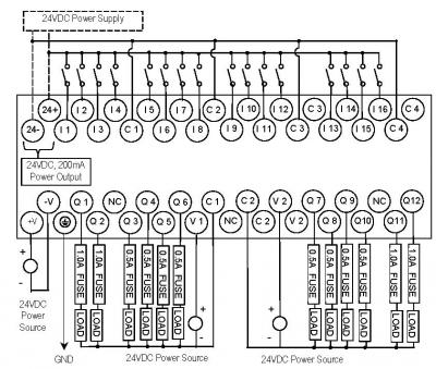

- #GE FANUC VERSAMAX PROGRAMMING CABLE RJ12 PINOUT MANUAL#
- #GE FANUC VERSAMAX PROGRAMMING CABLE RJ12 PINOUT SOFTWARE#
- #GE FANUC VERSAMAX PROGRAMMING CABLE RJ12 PINOUT SERIES#

Diagnostics: Status codes, command messages, and diagnostics.
#GE FANUC VERSAMAX PROGRAMMING CABLE RJ12 PINOUT SOFTWARE#
Software Reference: Command and register listing. Getting Started: Connecting the system, establishing communications with the amplifier, configuring the system. Installation: Heat load ratings, mounting and wiring. Hardware Overview: Product specifications, motor speed/torque curves. Before Operation: Unpacking and inspecting components, storage, and product part number reference. Chapter 2 Chapter 3 Chapter 4 Chapter 5 Chapter 6 Appendix A.
#GE FANUC VERSAMAX PROGRAMMING CABLE RJ12 PINOUT MANUAL#
All Rights Reserved.ģ Preface Content of This Manual Chapter 1.
#GE FANUC VERSAMAX PROGRAMMING CABLE RJ12 PINOUT SERIES#
Alarm Master Genius PowerMotion VersaMax CIMPLICITY Helpmate PowerTRAC VersaPro CIMPLICITY 90 ADS Logicmaster Series 90 VuMaster CIMSTAR Modelmaster Series Five Workmaster Field Control Motion Mate Series One FrameworX ProLoop Series Six GEnet PROMACRO Series Three Copyright GE Fanuc Automation North America, Inc. The following are trademarks of GE Fanuc Automation North America, Inc. No warranties of merchantability or fitness for purpose shall apply. GE Fanuc Automation makes no representation or warranty, expressed, implied, or statutory with respect to, and assumes no responsibility for the accuracy, completeness, sufficiency, or usefulness of the information contained herein. GE Fanuc Automation assumes no obligation of notice to holders of this document with respect to changes subsequently made. Features may be described herein which are not present in all hardware and software systems. While efforts have been made to be accurate, the information contained herein does not purport to cover all details or variations in hardware or software, nor to provide for every possible contingency in connection with installation, operation, or maintenance. This document is based on information available at the time of its publication. Note Notes merely call attention to information that is especially significant to understanding and operating the equipment. Caution Caution notices are used where equipment might be damaged if care is not taken. In situations where inattention could cause either personal injury or damage to equipment, a Warning notice is used. This cable has been designed to fit under the door of a Quantum CPU or NOM module.1 GE Fanuc Automation Programmable Control Products S2K Series Brushless Servo Amplifier User's Manual GFK-1866 September 2000 FANUC PLCsĢ Warnings, Cautions, and Notes as Used in this Publication GFL-002 Warning Warning notices are used in this publication to emphasize that hazardous voltages, currents, temperatures, or other conditions that could cause personal injury exist in this equipment or may be associated with its use. The following are the Modbus port pinout connections for nine-pin and 25-pin connections.Īlthough the Modbus ports electrically support existing Modbus cables, it is recommended that a Modbus programming cable (Part # 990NAA26320 or 990NAA26350) be used. The 140CPU53414B has a key switch with Run, Mem Prt, and Stop positions.Īll Quantum CPUs are equipped with a nine-pin RS-232 connector that supports Modicon’s proprietary Modbus communication protocol. On power-up, if you have a program in flash memory, you can choose the desired operating mode using the PLC MEM switch on the processor front panel. The CPU53414B has 1435KByte of Flash EPROM memory, which can be used to save the program and the initial values of variables. Schneider 140ACI04000 PLC Analog Input Module


 0 kommentar(er)
